In this tutorial you'll learn how to create a low poly ninja character model for games using Blender. The final model will be around 1,200 polys, which is a good amount for iphone or ipad games. Although this tutorial covers building the character in Blender, the workflow is universal and can easily be followed using any other 3D modeling/software package.
Additional Files/ Plugins:
Step 1
In a new file, select all the objects with the A key and then press Del to delete them.


The first step will be to add the background image for reference. With your mouse in the 3D view, hit N on the keyboard to bring out the Properties panel. Scroll down to the Background image panel and clik on 'Add Image'. Click Open and browse to select your image. The Background image is only viewable in 'Ortho' mode in the Left, Right, Top, Bottom, Front and Back views.


Step 2
Now we will start the character with the leg. Press Shift+A and add a Cylinder. In the Tool Shelf, reduce the vertices of the cylinder to 8 and the Cap fills to Nothing. We are making a low poly character so a cylinder with 8 vertices will be perfect. Press T the toggle Tool Shelf on/off.


Step 3
Press 1 on the Numpad to get into the front view. Then Press 5 to switch to ortho view, move the object to the center of the character so that we can get the center point of the cylinder (marked with the orange dot) at the center of the character. Select the object by Right-clicking and press G to grab, then move the mouse to move the object and Left click to confirm.


Now align the object from the side view as well. Press 3 on the numpad to get into the Right View. Select the cylinder with right click, press G and move the object. You can also use the widgets to move.


If you want, you can also split the 3D view into two, by dragging the top corner of the 3D window.


In the left 3D view, press 3 on the Numpad and set this as the Right view. You can skip this step if you prefer one view and only toggle it when necessary.


Step 4
In the Front view with the cylinder selected, press TAB to enter into Edit mode. Select all the vertices with the A key, and press G to move them to the ankle. We moved the cylinder in Edit mode because by doing this, we keep the object center (the orange dot) intact.


Step 5
With all the vertices selected, Press S to scale the Cylinder down to match the reference. Check from the side view also.


Step 6
In the Properties window, click on the Modifiers button and add a Mirror Modifier. This will automatically generate the mirrored symmetry on the other side of the object center.


Check the Clipping option. This will make the center vertices 'sticky'.


Step 7
Now we'll advance with the modeling. Select the top row of vertices using Alt-Right Click (you can also Drag Select with the B key.) Press Z to enable transparency so that you also select the vertices behind.


Press E to extrude the mesh and Left-click to confirm the position. The new row should be at the middle of the knee. Press S to scale to match the reference.


Step 8
Extrude again to the tip of the knee, and Scale to match the reference.


In the Side view (press 3 in the Numpad for the Right view), match the new edge loops with the reference. Select the edge loop using Alt+Right click, and move them with the G key. Scale accordingly Remember to scale ONLY in the Y-Axis as we already Scale-Matched in the Font view, so we don't want to disturb that. Press S and then Y to scale only in the Y-Axis.


Step 9
With this Extrude and Scale method, build up the leg of the character. At the end, Rotate the last Edge Loop with the R key. Remember to Save your file frequently with Ctrl+S.


Step 10
Check the mesh in the Side view as well. Remember while matching the loops with the Scale command, Scale only in the Y-Axis.


Step 11
Hold down the Shift Key and Right-Click on the middle five vertices to select them. Press E to Extrude them to the middle. As we had clipping ON in the Mirror Modifier, they will stick together.


Step 12
Select the top edge loop. Alt+Right-Click on the edge to select the complete loop. Press E to start extruding the body.


With the new row selected and in the Front view. Press S and then Z to scale the loop in the Z-Axis, so that the vertices are almost aligned in a line. Adjust the bottom vertices as well.


Step 13
Adjust the vertices of the newly formed loop to give it a nice round contour.


Step 14
Select the top edge loop and Extrude once more to form the waist line. Scale down the new edge loop in the Z-Axis to align them, and Move and Rotate to match the reference.


Step 15
Tweak the vertices in the side view to match the reference. You can select the whole edge loop using Alt+Right-Click, and then Scale them up in the Y-Axis.


Select the 2 vertices on the back part and pull them outward a bit. Tweak the rest of the vertices to get a nice round body.


Step 16
Select the top loop and with the same Extrude-Scale method, build up the body to the neck, matching the reference as you go.


Step 17
Adjust the loops in the side view as well, and Scale, Move and Rotate where necessary. Tweak the vertices to make the whole body smooth and round. It should not be 'cubic'.


Step 18
Place your mouse pointer between the two loops and press Control+R to create another edge loop. Click to confirm the position of the loop. Right-Click on the vertex shown in the image to select it, and delete it with DEL key. This will be the position from which we will extrude the arm.


Step 19
In the Side view adjust the vertices to get a nice round shape. You will notice that we automatically have 8 Vertices for the arm, just as we had for the leg.


Step 20
Select the front row of vertices with the B key (or multiple select using Shift+Right-Click) and the move them down to create some definition of chest. Use the G key to Move, you can toggle transparent mode with the Z key to select vertices which are behind. Pull the front two vertices up just a bit, as shown in the image.


Step 21
Alt+Right-Click on the edge loop to select all the vertices of the loop. Press E to start Extruding, and Left-Click to confirm. With the new loop selected, press S and X, then scale down the vertices to align them into a line. Left-click to confirm.


Step 22
Now we will Extrude this new loop to form the arm. You can Extrude and Scale them gradually, just like we did on the legs, OR, you can Extrude it to the end and then add edge loops in between and model the shape. We did the first method with the legs, so here we will practice the second method. With the New loop selected, press E to Extrude and Move the cursor to the base of the palm. And Left-Click to confirm. Scale and Rotate the new edge loop to match the reference.


Step 23
Now we will add extra edge loops to define the contour of the arm. Press Ctrl+R to bring out the loop. Then Left-Click to add the loop, and then Left-Click again to confirm the position (at the elbow.) Add three loops for the elbow joint. Rotate them if necessary to make them perpendicular to the arm.


Step 24
Add a few more loops (one for the tricep and one for the bicep.) Scale them to give some muscle definition. Add one more loop for the shoulder.


Step 25
Select the three vertices as shown and in the Top view, pull them a bit backward to that we have nice smooth shape, a smooth transition from back to shoulder to arm.


Similarly do this for the front three vertices as well.


You can also adjust the shoulder loop. Select the loop using Alt+Right-Click, and Scale them a bit in the Y-Axis. Press S and then Y to Scale only on the Y-Axis.


I have also adjusted the shoulder and neck from the Front as well.


Step 26
Lets move ahead and model the shoes. Select the bottom most edge loop and press E to Extrude it.


Step 27
Select the front two faces (four vertices from each face) and again press E to Extrude them.


Adjust and tweak the vertices to give it a nice shape of a foot/shoe.


Step 28
Select the two opposite edges and press F to make a face in between. Make one more face as shown in the image. Then hover your mouse over the new faces and press Ctrl+R to add a new edge loop, and Lift-Click to confirm. Select the two vertices as shown and press Alt+M to merge them. Do the same for the vertices at the heel.


Step 29
Now we'll start modeling the hand. Select the last edge loop using Alt+Right-Click, and then press E to Extrude it. Scale the new loop down a bit, and Extrude it again to form the wrist. Like all joints - knee, elbow, shoulder. We have 3 loops for the wrist too.


Step 30
Extrude it again to the knuckles, and Scale it down along the Z-Axis. Extrude and Scale down again to form the fingers. We need the model 'low poly', so no need to model the fingers separately. We will paint them over on the texture.


Step 31
Select the two edges shown, and press F to make a face to fill gap between them. You can select two vertices to select an edge, or press Ctrl+TAB and select Edge Select mode.


Step 32
Hover the mouse over the new face. Press Ctrl+R and Left-Click to make an edge loop. Select the two vertices on the side, and press Alt+M and Merge them in the center.


Pull the new edge outwards to get a smooth round end.


Step 33
Adjust the vertices from all views to give the palm some shape.


Step 34
Add a loop with Ctrl+R in the palm area. Select the two faces (one on the side and one on the adjacent bottom.) And Press E to Extrude out the thumb. Scale it down a bit with the S key, and Extrude again.


Step 35
Adjust the vertices and faces to form a good shape for the thumb.


And now we have the body ready.


Step 36
Let's begin the head. Press TAB to get out of Edit mode (body). Press Shift+A and add a new Cube.


Step 37
With the new cube selected, press TAB to Edit it. Press A to select all the vertices (if not already selected,) and then press W and click on Subdivide. Subdivide it one more time.


Step 38
Select all the vertices with the A key, and then Press Alt+Shift+S to execute the Spherify command. Drag your mouse (or Press 1) to make it a full sphere. You can toggle Local view with the / key, to hide other objects.


Step 39
Select the front four faces (hold Shift+Right-Click to select multiples,) then press E to Extrude. Extrude the faces inwards.


Scale down the new faces with the S key. And again Scale them up along the X-Axis to have a uniform edge thickness around them as shown.


Step 40
Select all the vertices again with the A key, and Scale to match the reference. Grab and Move them with the G key.


Step 41
In the front view (Press 1 on the Numpad), hit the B key and select all the vertices on the left side. Remember to select all the vertices which are behind as well, so press Z to toggle on the transparent view. Then Press DEL to delete them.


Step 42
With the head selected, go to the Modifiers panel and add a Mirror modifier.


Enable Clipping. This will keep the center vertices stuck together.


Step 43
Adjust and tweak the vertices to create a nice shape of head. Check from the Front view as well.


Step 44
Select the bottom vertex as shown and delete it.


Alt+Right-Click on the new edge loop to select it, and then press E to Extrude out the neck. Tweak the vertices to get round shape as shown.


Step 45
Press TAB to get out of Edit mode. Right-Click and select the head object first, and then the body. Hold Shift+Right-Click to multiple select. As both of them have a common modifier with the same Axis mirror, we can combine the two without removing the modifiers. With both objects selected, press Ctrl+J to join them. You might notice some shifting in the head or body.


If that happens, select only the head or the body by hovering the mouse over the desired mesh and Pressing L. Then you can move it around, Or you can just move the center edge loop. Make sure you have Clipping On in the mirror modifier first.


OR you can just move the center edge loop.


Step 46
De-select any vertices with the A key. Hover your mouse on the head and Press L. As this mesh is a separate group, all connecting vertices will be select. In short the head will be selected. Press G and move them up so that you can see some distance between the neck loops.


As you can see there is a difference in the number of vertices in the head's neck loop, and the body's neck loop.


You may add another loop in the head vertically. This will add two more vertices to the neck loop, resulting in a perfect match. However it will increase the polycount, we also can afford to have triangles in the neck area. So you can leave it as it is, and start stitching the two meshes.


Step 47
Press Ctrl+Tab and select 'Edge Select' mode. Select the two edges and press F to make a Face in between the edges.


Continue as shown in the image.


And fill out the remaining triangles.


Step 48
Press C and brush select the vertices of head and neck. You can increase or decrease the diameter of the selection brush with the mouse scroll wheel. Press G to Grab and Move them down, matching the reference. Use the Z key to enable transparent mode.


If you find an extra loop, select it and delete the edge loop. Tweak the rest of the head and move it closer to the body. Now you have complete the body! Don't forget to save the file with Ctrl+S.


Step 49
Now we will model some accessories like shoulder pads, etc. Select the faces above the shoulder and press Shift+D to duplicate them. Move your mouse so that they are above the shoulder, and then Left-Click to confirm the position.


Step 50
Select the edges and move them downwards. Hold Shift+Right-Click to multiple select, or press Alt+Right-Click to select the loop. And Press G to move.


Tweak the vertices to form a perfect shape.


If you like you can add more edge loops and re-shape it, but as we are making a fairly low poly model. We will keep the poly count as low as possible.


Step 51
For the gloves, add a loop on the forearm. Move the mouse over the forearm and press Ctrl+R to add a loop (click to confirm.) Then drag the mouse up to the desired position and left click again to confirm. Scale the new edge loop to achieve the thickness needed.


Step 52
Left just above the arm to position the 3D cursor, do the same in the side view as well. Any object we add will appear at this position.


Press Shift+A and add a Cone. Press T to bring out the tool shelf, and enter 3 in the vertices value.


Scale the cone down and rotate it, so that we have one single edge facing towards the fingers (see image).


Step 53
In the side view, select all the bottom vertices and press E to Extrude them down. Adjust the loops to get the desired shape.


Press 7 on the Numpad to get into the Top view, and then select the two faces as shown in the image. Press S and then Y to scale them down along the axis.


Step 54
Make sure to deselect any vertices by pressing the A key. Select any one vertex on this new cone mesh using Right-Click, and then press Ctrl+L to select all the linked vertices of this new cone. Scale, Rotate and Move it to the desired location. With the mesh selected, press Shift+D to make a duplicate, move the mouse to desired location and then Left-Click to confirm the position. Scale it down with the S key.


Step 55
If you want to add more definition to the trouser/pajamas, add an edge loop above the knee and Scale it.


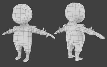
Step 56
Now you have the character model ready. Select all the vertices with the A key, and then press W to bring out the Specials menu. Select 'Shade Smooth' and Press TAB to exit edit mode. Finally Press Ctrl+S to save your file. The final model is around 12oo triangles.


Related Tutorials: